


American Society of Mechanical Engineers, ASME, is a not-for-profit professional organization that enables collaboration, knowledge sharing and skill development across all engineering disciplines, while promoting the vital role of the engineer in society. ASME helps the global engineering community develop solutions to real world challenges. ASME codes and standards, publications, conferences, continuing education and professional development programs provide a foundation for advancing technical knowledge and a safer world.
ASME 2013 Fluids Engineering Division Summer Meeting, that was held in Incline Village, NV, on July 2013, had attendance from colleagues in academia, industry and government, who will share their activities, ideas and advances in fluids engineering.
At the ASME 2013 Fluids Engineering Division Summer Meeting Upendra S. Rohatgi, Brookhaven National Laboratory, had presented the paper, that had arose as a result of joint work of Brookhaven National Laboratory (USA), National Metallurgical Academy of Ukraine, Materials Research Centre, Ltd.(Ukraine), American Energy Technologies Co. (USA), thanks to financial support of NNSA-DOE through GIPP project BNL-372 and STCU Partner project number P482.
ASME FEDSM2013-16630
STUDY OF AERODYNAMIC PROPERTIES OF CONTINUOUS HIGH TEMPERATURE REACTORS
Mykhailo V. Gubynskyi1, Igor V. Barsukov2,
Sergiy S. Fedorov1, Mykola V. Livitan1, Oleksiy G. Gogotsi3, Upendra Singh Rohatgi4
1National Metallurgical Academy of Ukraine, Dniepropetrovsk, Ukraine; 2American Energy Technologies
Co., Arlington Heights, IL, USA; 3Materials Research Centre, Ltd., Ukraine; 4Brookhaven National Laboratory, Upton, NY, USA
Keywords: carbonaceous materials; high temperature processing; recycling of spent battery materials
1. Introduction. In the last two decades the electrochemical energy storage devices community witnessed a colossal rate of growth with the lithium-ion battery market segment. From the worldwide sales of 400 million units per year in 1999, it leapfrogged to 1.1 billion batteries sold in 2005 [1], and then proceeded to the volume of shipments of 1.7 billion units in 2006 [2], and approximately 8.2 billion in 2011 [3].
; 4 – heat insulation; 5 – perforated distributor plate; 6 – fluidized bed; 7 – a system of product discharge coolers.") One of the key constituents of conventional lithium-ion batteries is premium quality graphitic carbon. An average cell, such as, for instance 18650 (65 mm tall by 18 mm diameter), could use approximately 10 grams of graphite in the negative electrode and up to 0.5 grams of graphite in the positive electrode. Consistent with market growth of end-use devices, the graphite market for lithium-ion batteries has been growing at a very healthy pace. Lithium-ion batteries consumed 3,000 tons of carbon in 2001, 6,000 tons in 2003, 11,000 tons in 2004 [4], while graphite consumption in 2012 was estimated to have exceeded 75,000 tons for a market value of near US $0.8 Billion.
One of the key constituents of conventional lithium-ion batteries is premium quality graphitic carbon. An average cell, such as, for instance 18650 (65 mm tall by 18 mm diameter), could use approximately 10 grams of graphite in the negative electrode and up to 0.5 grams of graphite in the positive electrode. Consistent with market growth of end-use devices, the graphite market for lithium-ion batteries has been growing at a very healthy pace. Lithium-ion batteries consumed 3,000 tons of carbon in 2001, 6,000 tons in 2003, 11,000 tons in 2004 [4], while graphite consumption in 2012 was estimated to have exceeded 75,000 tons for a market value of near US $0.8 Billion.
At this point of time Lithium-ion batteries consume exclusively primary graphite which is not being recycled and reused. In fact, presently majority of spent lithium-Ion batteries are being land filled by the waste processing giants. Land filling of batteries is associated with environmental concerns while it “leaves money on the table” by not recovering valuable battery materials that could be recovered, repaired and then sold to the battery manufacturers for a premium.
Currently, a handful of small companies upstream extract Cobalt from spent batteries and reduce the rest of batteries into slug by way of smelting. However, going forward, Cobalt-based chemistries will most likely be replaced with low cost alternative cathode compounds (e.g. LiFePO4, LiMn2O4 and their derivatives), which may not attract smelters any longer. This will likely be the triggering moment when interest in recycling and reuse of graphite will propel this mineral to near the top of the list of most lucrative materials for extraction. Authors of this paper are developing a commercially viable technology for beneficiation of graphitic carbons extracted from spent lithium-ion batteries. This paper introduces one of high temperature reactors which is being developed as part of this initiative.
2. Simulation Methodology and Discussion. It has been determined that prolonged cycling in lithium-ion batteries results in degrading graphite after use [5]. It was further seen that graphitic materials will fully repair their crystalline lattice properties when subjected to graphitizing heat treatment (e.g. at the temperature of 2,500+°C) [6,7]. A conventional approach to heat treatment of graphite at high temperatures comprises a variety of options in stagnant dense phase. Classic representative of the latter are Acheson furnaces which heat up to temperatures of up to 2,800°C by way of resistive heating of a stagnant batch of graphite, placed under cover of sand.
Furnaces which operate on principle of electrothermal fluidized bed can be regarded as a potentially more lucrative alternative to the process of high temperature treatment in dense bed. In order to achieve graphitization heat treatment of carbon material (e.g. ensure the heating is occurring on the order of 2,500-2,800°С) it is essential to use neutral gas atmosphere, such as Nitrogen, whose inertness excludes intense chemical interaction between the material and the oxidizers. The furnace, whose operating principal is depicted by Figure 1, could be used for high-temperature treatment.
The furnace is designed to operate in a continuous mode, with raw materials fed into the fluidized bed zone 6 continuously. For purpose of this project the particle size of feed material is 1-5 mm – a typical particle size, which comes from battery recycling process after a granulation step. The bed is heated by means of DC current. It passes between the central electrode (2) and the internal wall of the furnace, which serves the role of counter electrode (3). The flow of current between the electrodes becomes possible due to presence of electrically conductive particles in the bed space. These particles heat up and then, being gravity fed downwards, proceed into the water-cooled cooler (7) through the central opening in the gas distributor plate.
A series of subsequent cooling steps allow for unloading of purified material at the temperature which is low enough to safely handle and package upgraded graphite for future reuse purposes. Application of fluidized bed reactors for purification of granules addresses a number of fundamental technological tasks simultaneously which otherwise present unsurpassable challenges with other technologies. For instance, fluidized bed makes it possible to adjust electrical resistance of the bed as opposed to having to manage constant electrical resistance of the dense bed reactors.
Analysis of values of the material specific electric resistance in fluidized bed furnaces shows that in transfer from the dense bed to the fluidized bed the value of electric resistance rises by a factor of 4-7 and increases even further as the bed porosity grows. While undergoing processing, the increase in temperature and current results in reduction of electric resistance, partially due to en-process material repairing its graphitic properties.
 Another advantage of fluidized bed is its ability to instantly remove volatile and sublimed components through the flue in a process which continuously separates impurities from the end product. Separation in this case is driven by intense agitation of particles which constantly go through the rector and see a uniform heat gradient.
Graphitization heat treatment of carbon material in the furnace of the suggested design (Figure 2) is characterized by a change of the cross section of conducting bed with respect to its effective radius change. The minimum section area is related to the central electrode which is characterized by a radius r1. The maximum area refers to the inner radius of the peripheral electrode r2. As the cross section area increases, electric resistance changes, its value for the elementary bed electric resistance dR gets defined by 
where : R – electrical resistance, ρ - specific electrical resistance of the fluidized bed; S=2πrh – area of the bed perpendicular to the current direction; h – furnace working zone height. Assuming the total current value for any section within the bed is constant, the power distribution of heat sources under resistive heating equals to: 
Using the above approach we modeled the process inside fluidized bed. The solution to the model was defined as one-dimensional heat conductivity problem for the hollow cylinder with internal source of heat under adiabatic boundary conditions on its surfaces. It allowed estimating the rate of temperature drop across the radius of heated bed and temperature distribution for a given furnace operation mode. For calculations, we used the method of elementary heat balances and the method of iterations. The relation between specific electrical resistance and the temperature during the first stage was not taken into account and was assumed constant across the cross section of the bed. In our calculations it was equal to ρ=0.048 Ω·m.
To consider heat transfer in the fluidized bed, we used the value of coefficient heat conductivity λef, determined on the basis of equality between the diffusion coefficient and the coefficient of temperature conductivity of fluidized bed [8]. λef value varied in our calculations from 0.3W/(m·К) to 700 W/(m·К). The higher value of λef corresponded to the estimations reported in [8].
Significant values of the coefficient of effective conductivity of fluidized bed both in vertical and horizontal directions is determined by intensive circulation of material in the form of particle packets typical for developed modes of fluidization with bed porosity ε = 0.5-0.6. The minimum value of the effective coefficient of conductivity under investigation is characteristic for the dense bed of granular material, and it is determined by the value of heat conductivity of gas-filled voids between particles.
 Results of simulation modeling (Figure 3) testified that temperature drop across the bed section is determined by the value of effective heat conductivity and geometric dimensions of the fluidized bed (distance between the electrodes). Therefore, if there is no circulation in the bed (the mode of transition from dense bed stability to the state of instability), the temperature drop reaches 2,000-3,000єС, which makes stabilization of thermal treatment impossible. If the effective conductivity coefficient rises to 50-100 W/mК, the temperature drop decreases to a low ∆T= 50 - 200єС with the distance between electrodes being ∆R= 35-200 mm accordingly. Further increase in the heat conductivity of the bed results in gradual decrease in temperature drop to 4-25 єС .
Therefore, it is possible to realize high temperature treatment of carbon materials in electrothermal fluidized bed with coaxial disposition of electrodes in conditions of the proposed mode of fluidization. It is the process of material mixing that determines the choice of parameters for feed fluidizing gas.
3. Experimental verification of model parameters. An experimental method for determining the operational modes of the fluidized bed in small-scale prototype furnace having a throughput of 10 kg/hr has been described. A matrix of experimental investigations has been conducted in order to define peculiarities of transition to a fluidization state; study fluidization regimes which are possible in the furnace; model conditions for enabling the pulsing type fluidization; create a physical model of conditions which ensure intensive material agitation; analyze operational efficiency of the horizontal distributor plate.
The core of experimental unit presented by Figure 4 was comprised of a vertical tower (1) which has a diameter of 105 mm and a height of 1,000 mm. A perforated distributor plate (3) with the mesh opening #56 and the working area Sop=175.8 mm2 formed the foundation of the reactor. The central electrode (2) whose overall diameter is 45 mm was installed at a distance of 100 mm above the distributor plate. Figure 5 shows for reference a three-dimensional schematic of reactor 1. 
The upper part of the fluidization reactor is enlarged, by design, from Ø105mm tо Ø150mm and equipped with a scrubber (9) before the exhaust the processed air outside the laboratory. The air was fed with the help of turbo-air blower #4 of TG-0.25 type. The air consumption was measured in two points by means of throttling orifices and U- shaped manometers: point 5 from 0 to 15 m3/g and point 6 from 25 to 60 m3/g.
The following parameters were also measured: pressure drop at air consumption measuring points, excessive pressure under the distribution grid, height of the fixed bed, height of the fluidized bed, range and frequency of fluidized bed height change. Coefficient of effective heat conductivity of fluidized bed λef, W/mК ΔR=200мм ΔR=35мм 4.
For the purposes of this research, we used carbonaceous precursor with of the following fractions of size distribution: №1 – 0.8-2mm, №2 – 1-3mm, №3 – 2-5mm. The bed height in the static condition was 370-400mm which corresponded to the small-scale furnace (10 kg/h) operation and 20-minute exposure of the material to a heat zone.
 4. Results and Conclusions. Analysis of experimental results and observation of the bed behavior through site glass resulted in a conclusion that regardless of the investigated particle size fraction with model carbon material, the behavioral fluidization regimes in the developed reactor could be characterized by similar aerodynamic parameters.A description of typical fluidization regimes observed in our experiments is described below using as an example a size fraction of 0.8-2 mm. First of all, we were able to distinguish the following characteristic gas dynamic modes during experimental investigation (please see a schematic by Figure 6):
a) Immovable bed – material particles are immovable, the dense bed is negligibly agitated while the bed height increases by no higher than 5-10%;
b) Transition mode – small fractions of the bed particles begin to soar and the bed is divided into two parts: the immovable part of comprised of heavy weight particles and the airborne part in the state of bubbling-type fluidization;
c) Sub-standard bubbling mode – slowly circulating material is in the state of fluidization in the zone around the central electrode. Particles under the electrode are still immovable. Fluidization mode can be characterized as weak.
d) Intense bubbling mode – the height of fluidized bed is 1.5-2 times as high as that for the original bed depicted by Figure 6(a). Practically all the material is involved in circulation. Only 10-20 mm thick layer just above the distributor plate remains immovable. As gas bubbles percolate through the bed the effective height of the latter gets altered within А∆Р range that is 25-40% from the maximum attainable bed height. The height pulsation frequency and pressure drop ∆Р reaches values of 1-2 Hz.
The latter mode is characterized by intense mixing of the material in the entire bed space, which satisfies all the design requirements for consistency of uniform temperature zone in the working area of the furnace.
However, when considering the heat supply source of the furnace and selecting heating regime, it is necessary to take into account cyclic changes of the bed density and accordingly its electric resistance alteration within frequency range of 1-2 Hz. Assuming that electric resistance of the bed is directly related to its density, we were able to predict the current pulse change within the range of 25-40%. This may result in the decrease in furnace capacity and an excessive electric impact on the central electrode.
Table 1 presents recommended aerodynamic regimes of electrothermal fluidized bed which ensure consistent temperature zone of the material for all size fractions under investigation.
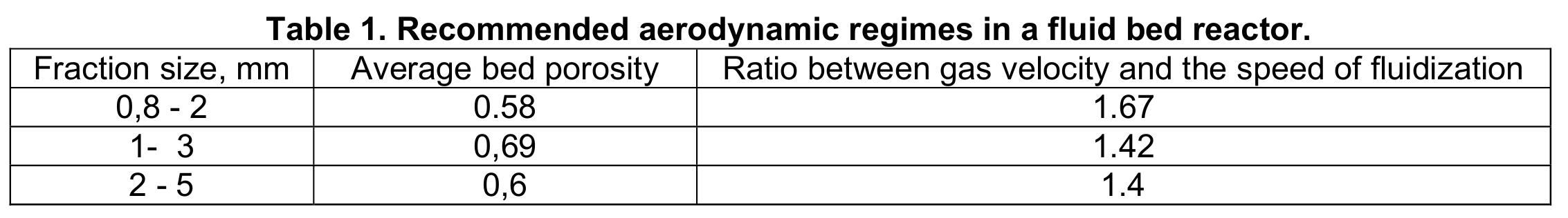
Figure 7 offers graphic depiction of four fluidization regimes described above (a, b, c and d). It shows the changes in aerodynamic resistance and porosity as function of gas flow rate.
A good understanding of the fluidization and change in resistance, and ability to adjust these parameters on a full scale operating reactor will be the key to enabling efficient and economically viable refining of graphitic carbons retrieved from spent lithium-ion batteries for purpose of their recycling and reuse.

Figure 6. Operational modes of fluidized bed reactor observed in experiment: а- Immovable bed, b – Transitional operating mode, с - Low-bubbling mode, d – Intense bubbling mode 1- electrode, 2-reactor, 3- fluidized bed, 4- perforated distribution grid, 5-overbed space, 6-agitating particles
 dependence of aerodynamic resistance as a function of fluidizing gas flow rate; ◊ - ε (W) dependence of average porosity of the fluid bed as a function of fluidizing gas flow rate; А∆Р – amplitude of frequencies of aerodynamic resistance of fluidized bed.")
Figure 7. Aerodynamic parameters of fluidized bed filled with particles sized d = 0,8-2,0 mm; a, b, c, and d – operating modes of fluidized bed from Figure 6. ▲ - ∆Р (W) dependence of aerodynamic resistance as a function of fluidizing gas flow rate; ◊ - ε (W) dependence of average porosity of the fluid bed as a function of fluidizing gas flow rate; А∆Р – amplitude of frequencies of aerodynamic resistance of fluidized bed.
References.
1. Handbook of Batteries. / D. Linden, T.B. Reddy.- 3rd ed. McGraw Hill, New York, NY, P.35.1 (2001).
2. Barry Huret, Battery Statistics. The Freedonia Group, Inc. (2006).
3. M. Tohani. Global Lithium-Ion battery market - Growth trends and application analysis. Frost & Sullivan Publ. 2, p.19 (2013).
4. I.V. Barsukov et al. (eds.), New Carbon Based Materials for Electrochemical Energy Storage Systems:Batteries, Supercapacitors and Fuel Cells. Springer, the Netherlands, P. 153 (2006).
5. W. Kohs, H.J. Santner, F. Hofer, H. Schrцttner, J. Doninger, I. Barsukov, H. Buqu, J.H. Albering, K.-C. Mцller,, J.O. Besenhard, M. Winter. A study on electrolyte interactions with graphite anodes exhibiting structures with various amounts of rhombohedral phase. J. Power Sources, v. 119-121, P. 528-537(2003).
6. M.V. Gubynskyi, S.S. Fedorov, M.V. Livitan, I.V. Barsukov, O.G. Gogotsi, N.P. Brodnikovskiy. Furnaces for manufacture of high purity carbonaceous materials. Book of Proc. of Conference: "Theory and Applications of Heat Processes in Metallurgy". 18-21/9/2012, URFU Publ., Yekateringburg, Russia, p.79-83 (2012) – in Russian.
7. Y. Reynier, R. Yazami, B. Fultz, I. Barsukov. Evolution of lithiation thermodynamics with thegraphitization of carbons. J. Power Sources. 165 P. 552-558 (2007).
8. A.I. Malinovskiy, O.S. Rabinovich, V.A. Borodulya, A. Zh. Grebenkov, and A.M. Sidorovich. Local conductivity of fluidized bed filled with electrically conductive particles. Journal of Engineering Physics. V.85, N 2, p. 239 – 245 (2012) – in Russian. 9. O.M. Todes and O.B. Tsitovich. Fluidized bed reactors. Leningrad, Khimiya Publ. House. P. 296 (1981)– in Russian.
Nomenclature
H Height of Fluidized bed
I Current
N Power
R Ele ctric Resistance
ε Porosity
ρ Specific Electric Resistance
λ Effective Heat Conductivity
Acknowledgements:
Authors are sincerely grateful for support from Dr. Joseph E. Doninger of Dontech Global, Inc. in Lake Forest, IL, USA and Robert Aronsson of Apollo Energy Systems of Pompano Beach, FL, USA during various stages of this project. Additionally we would like to acknowledge scientific contributions by the engineering group represented by Vitaliy I. Lutsenko, Yaroslav O. Tyrygin, Konstantyn A. Nikitenko and Vadim Yu. Pisarenko of M.K. Yangel Special Design Bureau “Yuzhnoe” in Ukraine who are also taking part in this project. Authors also. acknowledge the financial support of NNSA-DOE through GIPP project BNL-372 and STCU Partner project number P482. Authors further wish to thank STCU’s Lead Expert Natalia N. Dudko and Yulia B. Chetvertak for their project support.

 Our collaborative work on porous Ti₃AlC₂ MAX phase for efficient Ti₃C₂Tₓ MXene synthesis has been ranked among the Top 10 most cited papers in the International Journal of Applied Ceramic Technology (IJACT).
 We highly recommend checking out new important paper: “Critical Assessment of Intrinsic Antibacterial Properties and Photothermal Therapy Potential of MXene Nanosheets.” Along with the key findings, we’re also excited to share the Supplementary Cover Art — it beautifully illustrates our vision of MXene-based targeted complexes that can eliminate bacteria via photothermal conversion under near-infrared irradiation.
 Do MXene nanosheets possess intrinsic antibacterial activity? A systematic study of high-quality Ti-, V-, and Nb-based MXenes reveals negligible inherent antimicrobial effects while highlighting their strong potential for targeted photothermal antibacterial therapy.
 Highlights
") We are excited to share that our Carbon-Ukraine (Y-Carbon LLC) company participated in the I2DM Summit and Expo 2025 at Khalifa University in Abu-Dhabi! Huge thanks to Research & Innovation Center for Graphene and 2D Materials (RIC2D) for hosting such a high-level event.It was an incredible opportunity to meet brilliant researchers and innovators working on the next generation of 2D materials. The insights and energy from the summit will definitely drive new ideas in our own development.
We are excited to share that our Carbon-Ukraine (Y-Carbon LLC) company participated in the I2DM Summit and Expo 2025 at Khalifa University in Abu-Dhabi! Huge thanks to Research & Innovation Center for Graphene and 2D Materials (RIC2D) for hosting such a high-level event.It was an incredible opportunity to meet brilliant researchers and innovators working on the next generation of 2D materials. The insights and energy from the summit will definitely drive new ideas in our own development. Carbon-Ukraine team had the unique opportunity to visit XPANCEO - a Dubai-based deep tech startup company that is developing the first smart contact lenses with AR vision and health monitoring features, working on truly cutting-edge developments.
 Our Carbon-Ukraine team (Y-Carbon LLC) are thrilled to start a new RIC2D project MX-Innovation in collaboration with Drexel University Yury Gogotsi and Khalifa University! Amazing lab tours to project collaborators from Khalifa University, great discussions, strong networking, and a wonderful platform for future collaboration.
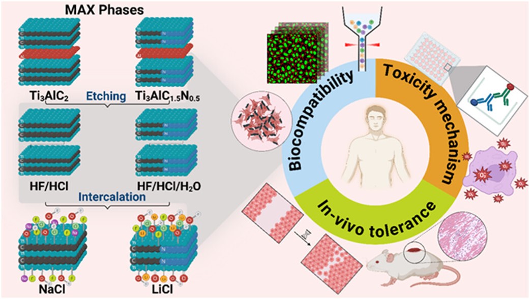 MXenes potential applications include sensors, wound healing materials, and drug delivery systems. A recent study explored how different synthesis methods affect the safety and performance of MXenes. By comparing etching conditions and intercalation strategies, researchers discovered that fine-tuning the surface chemistry of MXenes plays a crucial role in improving biocompatibility. These results provide practical guidelines for developing safer MXenes and bring the field one step closer to real biomedical applications.
. 2D MXenes in the design of heavy metal ion sensors (Review). Trends in Environmental Analytical Chemistry, 47, e00270. DOI:10.1016/j.teac.2025.e00270") An excellent review highlighting how MXene-based sensors can help tackle one of today’s pressing environmental challenges — heavy metal contamination. Excited to see such impactful work moving the field of environmental monitoring and sensor technology forward!
An excellent review highlighting how MXene-based sensors can help tackle one of today’s pressing environmental challenges — heavy metal contamination. Excited to see such impactful work moving the field of environmental monitoring and sensor technology forward!
 Carbon-Ukraine team was truly delighted to take part in the kickoff meeting of the ATHENA Project (Advanced Digital Engineering Methods to Design MXene-based Nanocomposites for Electro-Magnetic Interference Shielding in Space), supported by NATO through the Science for Peace and Security Programme.
 Exellent news, our joint patent application with Drexel University on highly porous MAX phase precursor for MXene synthesis published. Congratulations and thanks to all team involved!
 Our team was very delighted to take part in International Symposium "The MXene Frontier: Transformative Nanomaterials Shaping the Future" – the largest MXene event in Europe this year!
  Last Call! Have you submitted your abstract for IEEE NAP-2025 yet? Join us at the International Symposium on "The MXene Frontier: Transformative Nanomaterials Shaping the Future" – the largest MXene-focused conference in Europe this year! Final Submission Deadline: May 15, 2025. Don’t miss this exclusive opportunity to showcase your research and engage with world leaders in the MXene field!